
SHEFFIELD / HYPOTHETICAL DESIGN STUDIES
A small change. A different question.
Two independently invented scenarios explore material, form and print orientation. They are not customer projects, manufactured samples or measured results. Illustration geometry is explanatory, not ready-to-print CAD.
HYPOTHETICAL DESIGN STUDY / 01
Bend it, or split it?

- 1. OpeningCompare the entry gap with the cable and connector route.
- 2. ContactDecide which surfaces may touch the cable jacket.
- 3. SplitAllow removal and access to the fastening method.
A / Flexible open clip
Opening depends on movement in the body. Ask how far the arms must move and where the cable jacket will touch.
B / Rigid split form
Opening happens at a joint. Ask how the cap is removed, how the fastening method is reached and what prevents pinching.
Hypothetical design study — flexible cable clip.
Fictional brief
Imagine a removable organiser for one loose desk cable. It should make the cable easy to find without clamping its jacket tightly. Assume an indoor desktop and occasional insertion/removal. Cable diameter, connector size, wall thickness, exact grade and required service life are deliberately unspecified. This is not a mains strain-relief, load-bearing clamp or electrical safety component.
Two approaches
A — flexible open clip. A one-piece C-shaped body could open through elastic movement. A wider entry and rounded contact area could make insertion more gradual. The opening, arm length and cross-section need to be considered with the chosen flexible grade; a hardness label alone does not specify how this shape will behave.
B — rigid split form. A lower cradle and removable upper half could enclose the cable without asking the main body to flex during insertion. This adds a joint, access for a fastening method and a separate piece to handle. The illustrated holes only suggest removable screws: screw size, inserts or nuts, tightening limits and clearances are not defined.
The practical comparison is a method of opening: bend a part, or open a joint. Neither concept is selected as suitable yet. Prusa’s flexible-material guidance identifies both geometry/settings and support removal as relevant constraints; this fictional application of those points is our own reasoning. Flexible materials.
What the illustration shows
- Opening: compare the cable and connector route with the entry gap; no forced-fit dimension is implied.
- Contact: identify where the jacket touches, and the movement needed without damaging it.
- Split: provide a way to open the rigid alternative and access its fastening method.
Conditions to questions
| Condition | Flexible concept | Rigid split-form concept |
|---|---|---|
| How the cable enters | How far must the arms move? Can the connector pass another way? | Is there room to remove the cap and handle the fasteners? |
| Repeated opening | What deformation and number of uses should a later trial represent? | How often will the joint open, and what could loosen or wear? |
| Cable protection | Where are the contact patches and edges? | What stops fastening force from pinching the jacket? |
| Heat and cleaning | Which actual grade and exposure data apply? | Which grade and joint materials face the same exposure? |
| Space and attachment | Is the clip free-standing or attached, and by what method? | Does the joint fit within the permitted envelope? |
What would need confirming
Measure the cable and connector envelope; specify permitted movement, attachment, contact surfaces, expected environment, opening frequency and quantity. Choose the actual grade and orientation, then agree what a physical sample needs to demonstrate. Insertion/removal, recovery after movement and cable-surface effects would need suitable checks before manufacture for the intended use. No such checks have been carried out here.
A manufacturer’s TPU data sheet reports results for specified specimens and conditions. Its elongation-at-break figure is not a safe recurring strain or clip-cycle-life rating. Do not transplant it into this design. UltiMaker TPU 95A technical data sheet.
Send for a quote
Provide the model and units, cable/connector measurements, quantity and the intended opening method. Identify the question still unresolved. If the geometry is not settled, start with a CAD enquiry; a picture of this concept is not a printable model. Materials & preparation · CAD design & modelling · Get a Quote.
HYPOTHETICAL DESIGN STUDY / 02
Thin profile, or a rib?

- 1. PivotDefine the axis and neighbouring clearances.
- 2. SectionExtra depth changes the shape and space required.
- 3. InputSpecify force location, direction and permitted movement.
A / Thin profile
A shallow section could fit a restricted space. Its appearance does not establish stiffness or suitability.
B / Deeper rib
A rib changes the section and occupies more space. Any benefit depends on the intended load and the rest of the design.
Hypothetical design study — rigid lever form comparison.
Fictional brief
Imagine a small hand-operated lever for a non-critical desktop mechanism. A circular hole locates a pivot, and the narrow end receives a light manual action. The exact force, direction, travel, lever length, pivot hardware and life requirement are not specified. This is an educational form comparison, not a design for machinery guarding, lifting or any critical function.
Two approaches
A — thin flat profile. A simple plate could suit a shallow space and expose few features for support preparation. Its thickness still needs to be chosen for the actual load and allowed movement. A thin appearance does not tell us its stiffness or strength.
B — deeper ribbed profile. A rib places additional material farther from part of the section’s centre and could reduce bending in an intended direction. It occupies more space and changes the rib-to-body transition, pivot surroundings and print preparation. That conditional mechanics inference is not a measured improvement; a rib can be ineffective for a different load direction.
The comparison is incomplete if one version also changes grade, wall settings or loading. Set those conditions deliberately before attributing any future difference to the rib. Smooth transitions may help avoid abrupt stress concentrations; the cited manufacturer’s FDM guidance discusses fillets, but supplies no validated dimensions for this fictional part. Stratasys FDM design guide.
What the illustration shows
- Pivot: define its axis, hole/shaft relationship and clearance to neighbouring parts.
- Section: compare the thin plate with the deeper longitudinal rib; colours are identification only.
- Input: mark where the hand or mechanism acts and in which direction.
Orientation is a separate decision
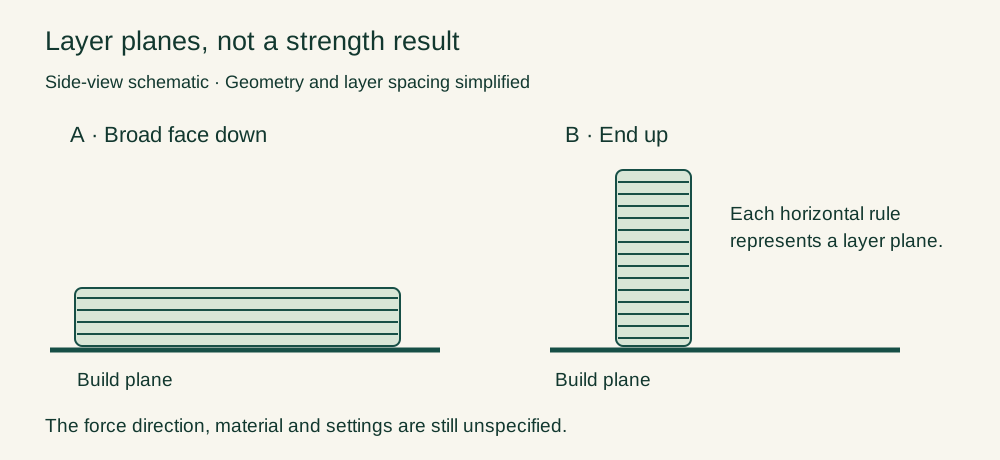
The second illustration places a lever form broad-face-down and end-up. Each layer remains parallel to the build plane, so the direction of the interfaces within the finished part changes. FDM properties can depend on direction; support access and surface finish also matter. A visually convenient position is not automatically the appropriate one. Stratasys orientation discussion.
Do not infer “flat is always stronger” or “more infill fixes every load”. For this example, a drawing showing the pivot support and force direction would be needed before proposing an orientation. The diagram below clarifies the simplified layer planes without claiming to be a slicer result.
Conditions to questions
| Condition | Question before choosing a form or orientation |
|---|---|
| Force and support | Where is the pivot constrained, and is force in or out of the lever’s broad plane? |
| Allowed movement | How much bending, twisting or play can the mechanism tolerate? |
| Available space | Can a rib pass neighbouring parts throughout the full travel? |
| Repeat use | What loading sequence and duration should a future evaluation represent? |
| Material and process | Which grade, section, wall settings and layer direction define the comparison? |
| Surface and fit | Which hole or bearing/contact face matters, and could support removal affect it? |
What would need confirming
Supply a dimensioned model, pivot hardware, force location/direction, travel, envelope, use frequency, environment and quantity. Agree the material and print preparation. A later sample would need appropriate fit, free-movement, deflection and repeat-use evaluation for its intended job. No such physical evaluation is represented by this study.
Send for a quote
Send both model variants if the purpose is comparison, identify the controlled differences, and include a simple marked loading sketch. Use a CAD enquiry if the rib, pivot or mating geometry still needs designing. Explore functional parts and materials & preparation, or get a quote for a ready model.

Prepare your own brief with the blank conditions outline. Use materials and orientation guidance to identify what is known and what still needs deciding.